
Product Overview
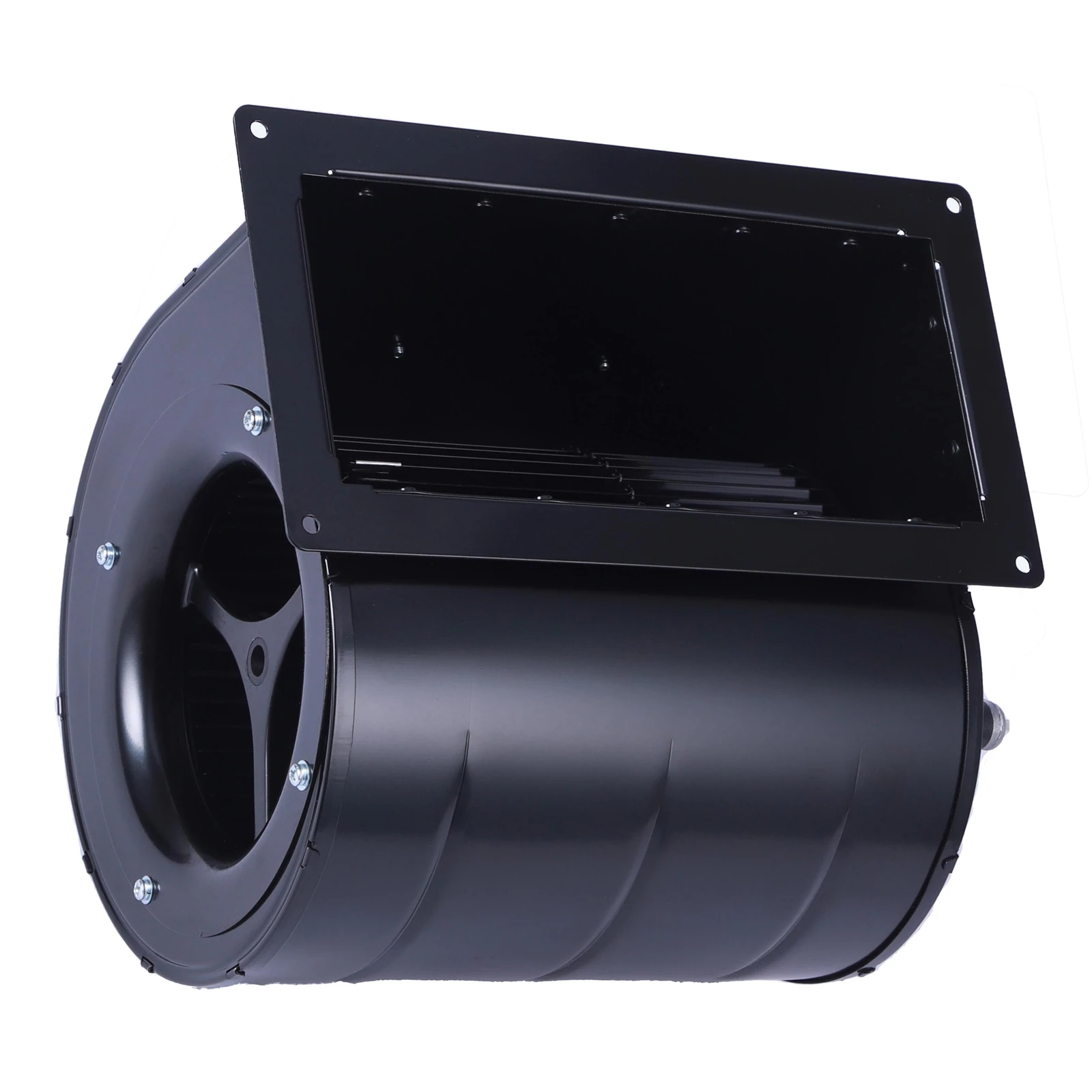
SF133A-E092A3-01 is an EC centrifugal fan with a 230 Vac input, delivering 1150 m³/h at up to 485 Pa, 125 W, 1800 r/min, 66±2 dB(A). Used in AHUs, fan coils, range hoods, air purifiers and ERV units. USD 42–85 FOB Nansha, MOQ 80 pcs, 25–30 days.
- Compact industrial housing (IP54)
- Long-life NSK ball bearings
Selection notes
SF133A-E092A3-01 belongs to the SF133A range: a EC centrifugal fan rated 230 V AC, 1150 m³/h at up to 485 Pa, 1800 r/min. Speed is set through 0-10V/PWM, 0-5V, 0-6.5V, 4-speed; the datasheet sound pressure is 66±2 dB(A).
Duty point: 1150 m³/h at 485 Pa. Because speed can be trimmed through 0-10V/PWM, 0-5V, 0-6.5V, 4-speed, the same unit can be re-set on site if the measured system resistance differs from the design value. For the destination market the grid is typically 110–240 V, 50/60 Hz, with CE, UL/ETL or CCC depending on destination as the compliance framework.
Technical Specifications
| Category | Centrifugal Fan |
|---|---|
| Model | SF133A-E092A3-01 |
| Motor Type | EC |
| Airflow | 1150 m³/h |
| Max Static Pressure | 485 Pa |
| Voltage | 230 V AC |
| Power | 125 W |
| Current | 0.54 A |
| Speed | 1800 r/min |
| Noise | 66±2 dB(A) |
| Protection Class | IP54 |
| Working Temperature | -25 °C ~ +60 °C |
| Impeller Material | Galvanised sheet steel |
| Bearing Type | NSK ball bearing |
| Speed Control | 0-10V/PWM, 0-5V, 0-6.5V, 4-speed |
Data updated 2026-10
Ordering Information
| MOQ (Min. Order Qty) | 80 PCS |
|---|---|
| FOB Price | FOB Nansha Guangzhou |
| Reference price | US$42–85 |
| Lead Time | 25-30 days |
| Sample | Sample available |
| Payment Terms | TT |
| Shipping Port | Nansha Guangzhou OR Yantian Shenzhen |
Other Models in This Series
Performance Curves
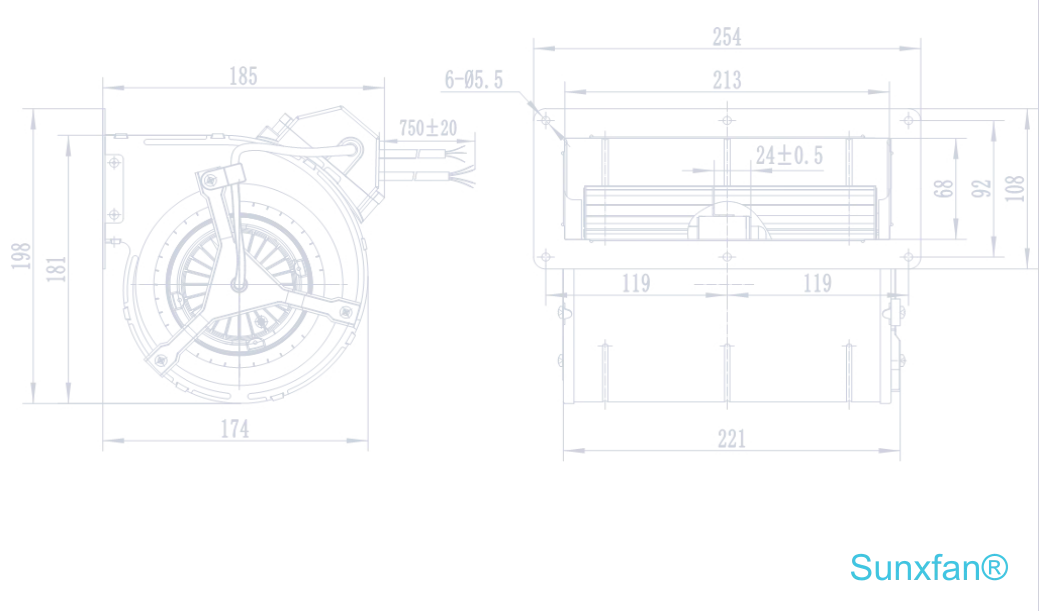
Dimensions
Special Remarks
[Optional] Housing and impeller material: galvanized steel plate + electrophoretic black.
Applications
133×133 mm dual-inlet EC blowers delivering 1,150 m³/h at 485 Pa — the airflow of a much larger wheel in an ultra-flat format for slim air curtains, wall-mounted ERVs and underfloor fan coils. 115/230 V AC or 310 V DC, IP54.
Product dataSheets (PDF Download)
View Product dataSheets (PDF) PDF · EC·Centrifugal fan:SF133A-E092A3-01 Product dataSheetsFrequently Asked Questions
How to replace a conventional AC blower with an external rotor EC centrifugal fan?
Replacing a conventional AC blower with an external rotor EC centrifugal fan requires bypassing external frequency drives (VFDs), connecting mains AC power directly to the EC motor's built-in controller, and wiring low-voltage control signals (0–10V, PWM, or Modbus RTU) for speed modulation. Because external rotor EC fans feature an integrated motor-and-drive package, they serve as a direct mechanical drop-in while eliminating external inverter cabinets and reducing energy consumption by 30%–50%. [Electrical Safety HazardAlways disconnect main supply power and wait at least 5 minutes for internal drive capacitors to discharge before handling motor terminals or power wiring.] 1.Isolate Power & Remove Legacy AC Drive Controls:Prerequisite。Turn off and lock out main system power. Disconnect the legacy AC blower and bypass or remove external VFDs or voltage transformers. EC motors feature built-in inverter electronics, rendering external frequency drives redundant. 2.Mount the External Rotor EC Fan:Mechanical Retrofit。Unbolt the existing AC fan assembly. Align and secure the external rotor EC centrifugal fan using standard mounting brackets or scroll housing flanges. Ensure exact clearance between the inlet cone and impeller to avoid aerodynamic loss or contact. 3.Wire Direct Line Power Supply:High-Voltage Wiring。Connect line power (115V AC or 230V AC) directly to the EC motor’s main supply terminals (L, N, PE Or L1/L2/L3). Ensure the Protective Earth (PE) ground wire is securely bonded to the chassis to protect internal drive electronics. 4.Connect Control & Signal Wiring:Low-Voltage Interface。Wire the low-voltage control cable to the EC driver’s signal terminal block:0–10V / PWM: Connect the positive control signal to 0–10V/PWM Input and reference ground to GND.Modbus RTU: Connect RS485-A and RS485-B lines for digital networking and telemetry.Potentiometer: Use the internal +10V DC supply output if controlling speed locally. 5.Commission & Verify Operation:Functional Test。 Apply power and send a low control signal (~2V or 20% PWM command). Verify that the fan soft-starts smoothly, rotates in the correct direction, and responds proportionally across the full control range. Verification: A successful replacement is confirmed when the fan soft-starts without electromagnetic hum, modulates speed smoothly following the 0–10V/Modbus signal, and maintains required static pressure with significantly reduced motor heat.