
Introduction: The Datasheet Says 35 dB(A) — Why Is It Louder Once Installed?
Almost every fan datasheet carries a line reading “Noise: ≤35 dB(A)”. But once the fan goes into the finished equipment, what the ear hears rarely matches that number — sometimes it is louder, sometimes it is irritatingly loud, and sometimes the decibel reading is modest yet the sound is simply annoying.
The problem is not that manufacturers fudge the numbers. It is that “noise” is not an intrinsic property of the fan — it is the combined result of fan + system + human ear.
This deep dive untangles it in four steps:
- How sound is quantified (what a decibel actually measures)
- How the human ear “rewrites” the measurement (A-weighting, phon, sone)
- Where fan noise comes from (three sources: aerodynamic, mechanical, electromagnetic)
- How to genuinely reduce noise through fan selection and system design
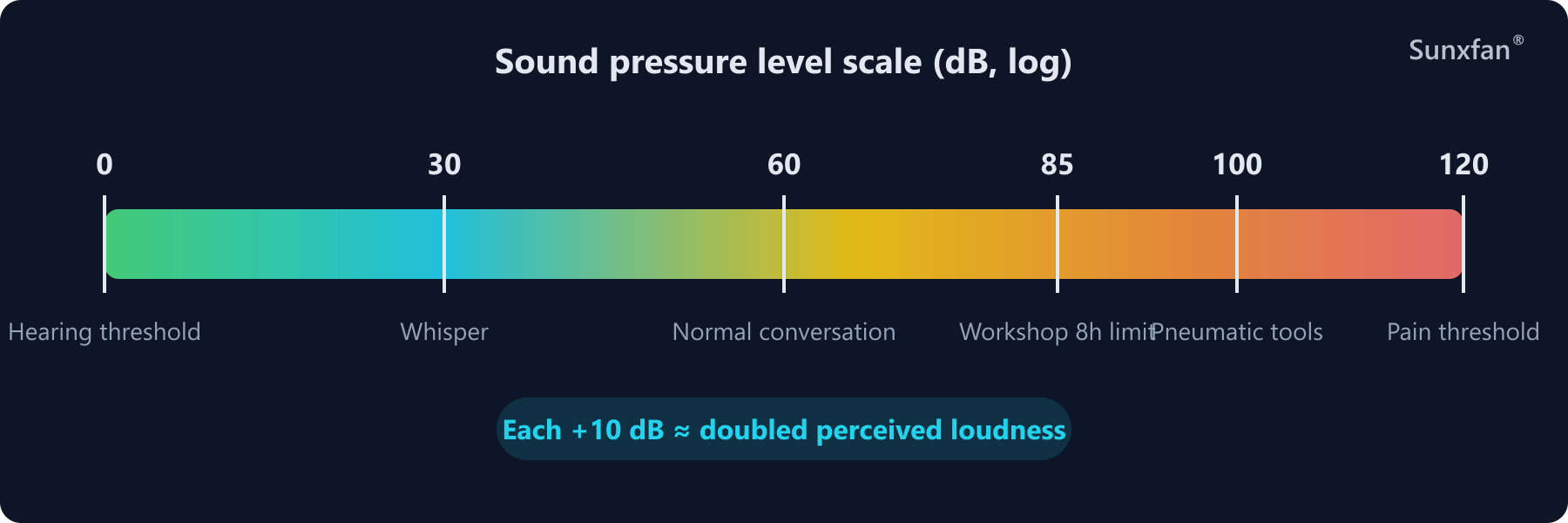
Figure 1 · The SPL ruler: on a logarithmic scale, every +10 dB roughly doubles the perceived loudness
1. The Decibel: A Counter-Intuitive Unit
1.1 Why Sound Pressure Level Uses a Logarithm
The audible sound pressure range of the human ear runs from 20 µPa (threshold of hearing) to about 20 Pa (threshold of pain) — a span of one million times. Describing it in pascals is both unwieldy and out of step with how the ear perceives loudness, so acoustics uses the Sound Pressure Level (SPL):
Lp = 20 × log10(p / p₀)    unit: dB
p₀ = 20 µPa (human hearing threshold at 1000 Hz)
The logarithmic scale leads to two corollaries you must remember:
- A 10× increase in sound pressure adds only 20 dB to the SPL
- A doubling of energy adds only 3 dB — this is the cornerstone of the “multiple fans” summation math later on
1.2 Decibels Cannot Be Added Directly
Two 40 dB fans do not make 80 dB. They make:
L_total = 10 × log10(10^(40/10) + 10^(40/10)) = 40 + 3 = 43 dBQuick formula for summing identical fans:
L_total = L_single + 10 × log10(N)| Number of fans N | Noise increment |
|---|---|
| 2 | +3.0 dB |
| 3 | +4.8 dB |
| 4 | +6.0 dB |
| 8 | +9.0 dB |
| 10 | +10.0 dB |
For fans of different ratings, use energy summation: for example, three fans at 55 dB, 60 dB and 65 dB sharing one system:
L = 10 × log10(10^5.5 + 10^6.0 + 10^6.5) ≈ 66.5 dBA counter-intuitive but extremely useful conclusion: switch off the 65 dB unit and the total drops by only about 1.5 dB. When multiple noise sources sum together, the total level is dominated almost entirely by the loudest one — noise reduction means attacking the main contributor first.
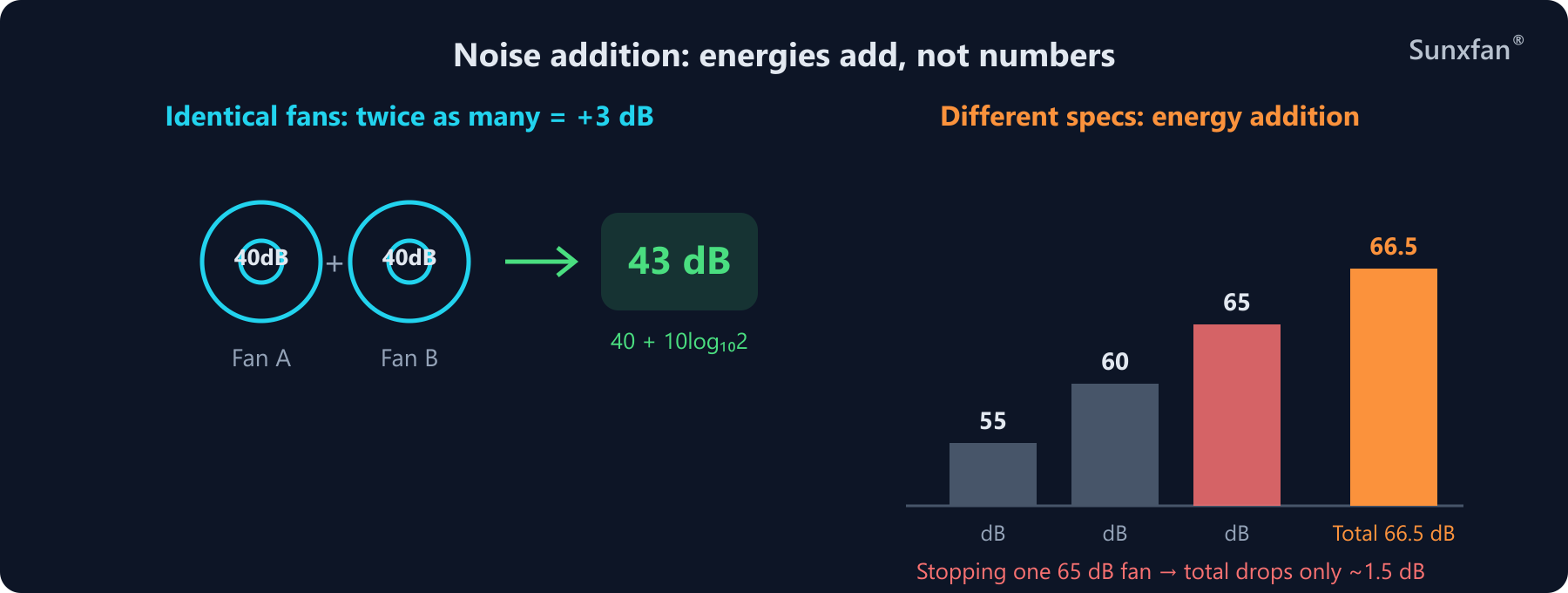
Figure 2 · Summing noise: doubling identical fans adds only +3 dB; different ratings sum by energy, with the total dominated by the loudest source
2. The Human Ear Is Not a Microphone: A-Weighting, phon and sone
2.1 Equal-Loudness Contours: The Ear’s Factory Settings
The ear’s sensitivity varies enormously across frequencies, a characteristic described by equal-loudness contours:
- The ear is most sensitive in the 1–4 kHz band (exactly the range of screams and alarms — an evolutionary trait)
- Low frequencies are barely registered: a 30 Hz pure tone must be about 50 dB louder than a 1 kHz tone to sound equally loud
- High frequencies above 10 kHz are likewise dull to the ear
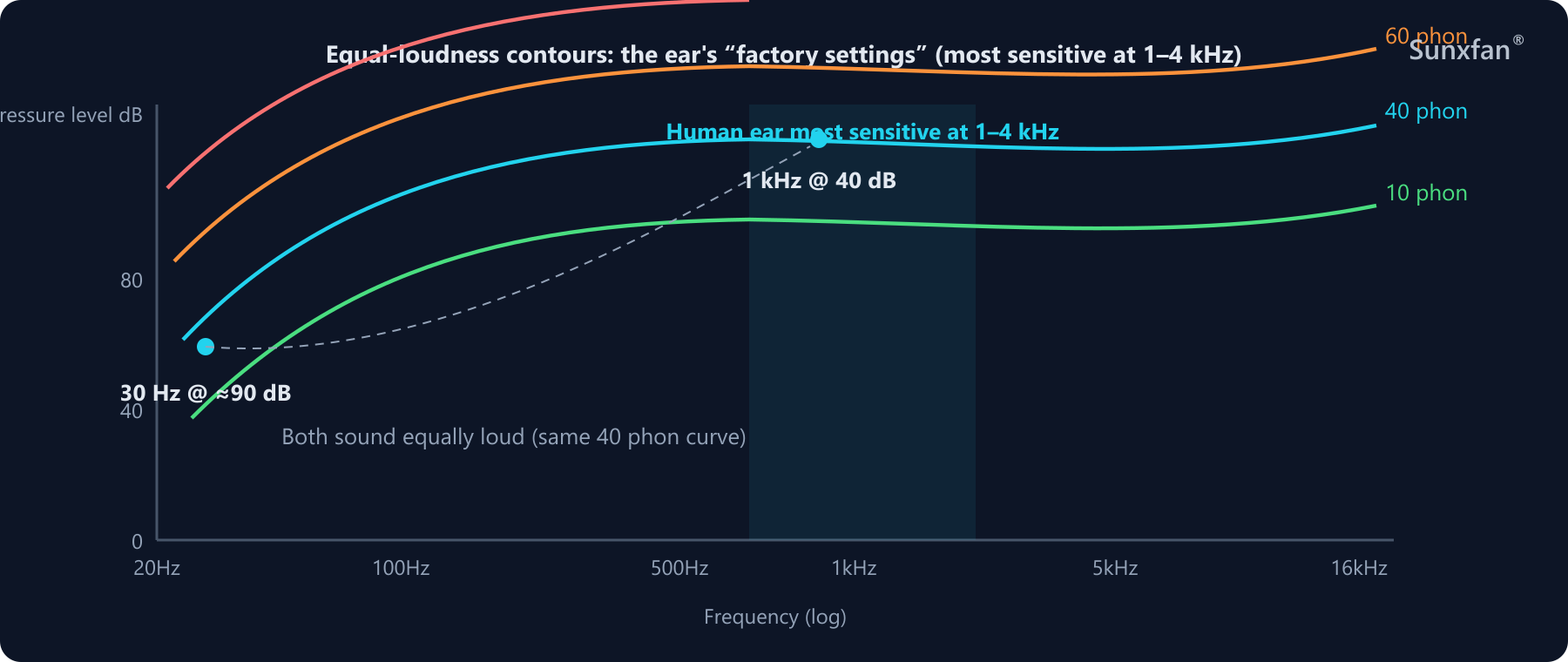
Figure 3 · Equal-loudness contours: the ear is most sensitive at 1–4 kHz; a 30 Hz tone needs about 50 dB more level than 1 kHz to sound equally loud
2.2 A-Weighting: Fitting the Microphone with an “Ear Filter”
Since instruments and ears “listen” differently, engineering introduces frequency weighting networks. The most common is A-weighting: based on the 40-phon equal-loudness curve, it corrects each frequency band of the measured spectrum and then sums the band energies:
LA = 10 × log10( Σ 10^((Li + Ci)/10) )
Li: SPL of the i-th band    Ci: A-weighting correction for that band
Typical corrections:
| Frequency | A-weighting correction |
|---|---|
| 50 Hz | −30.2 dB (heavily attenuated) |
| 500 Hz | −3.2 dB |
| 1–4 kHz | ≈ 0 (passed through unchanged) |
| 10 kHz+ | slightly attenuated |
So the meaning of dB(A) is: roughly how loud this equipment’s noise sounds to a human ear. It is fast, cheap and reproducible — the common language of datasheets, regulations and quality inspection.
2.3 phon and sone: The Language of Psychoacoustics
A-weighting is still a one-size-fits-all simplification. To quantify “human perception” more precisely, there are two further scales:
| Scale | Unit | Definition | Framework |
|---|---|---|---|
| Sound pressure level (weighted) | dB(A) | Corrected physical sound pressure | Engineering acoustics |
| Loudness level | phon | SPL of a 1 kHz pure tone judged equally loud | Physical scale |
| Loudness | sone | 1 sone = 40 phon; every +10 phon doubles the sone value | Psychoacoustics |
Loudness conversion: N = 2^((L−40)/10) — i.e. 40 phon = 1 sone,
50 phon = 2 sone, 60 phon = 4 sone.
2.4 dBA Is the “80% Solution”
Field experience from thermal design practice:
- SPL (dBA) rises logarithmically with speed and approaches a ceiling
- Loudness (sone) rises exponentially with speed — measurements have shown cases where SPL increased 10 dB(A) while loudness tripled
Rules of thumb for engineering practice:
- Evaluating a fan on its own → dB(A) is enough
- Similar dBA but one clearly sounds “noisier” → bring in psychoacoustic metrics: loudness (sone), sharpness, fluctuation strength
- When dBA values differ widely, loudness usually differs widely too — which is why dBA remains the first screening filter
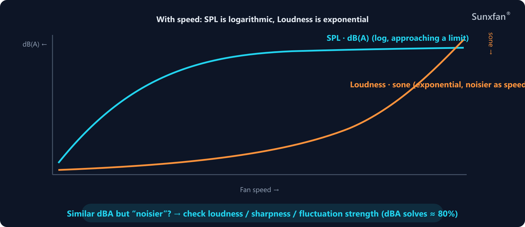
Figure 4 · SPL (dBA) climbs gently and logarithmically with speed while loudness (sone) rises steeply and exponentially — dBA is the “80% solution”
3. Where Fan Noise Comes From: Three Sources
3.1 Aerodynamic Noise (The Main Actor)
Rotating blades periodically disturb the air and create pressure fluctuations — the fundamental origin of fan noise. Its most recognizable component is the blade-passing frequency (BPF):
BPF = n × Z / 60    (Hz)
n: rotational speed (rpm)    Z: number of blades
Example: a 6-blade fan at 2800 rpm has BPF = 2800 × 6 / 60 = 280 Hz, and its higher harmonics fall right in the ear’s most sensitive range — that is the source of the “whiiiine” tone. Beyond it there is also:
- Turbulence noise: boundary-layer separation on blade surfaces and trailing-edge vortex shedding — a broadband “whoosh”
- Inlet/outlet interaction noise: the smaller the gap between the impeller and the scroll tongue or struts, the sharper the whine
- Stall noise: operating away from the design duty point throws the flow angle of attack off and raises the noise level markedly
This is the acoustic explanation of why the fan’s operating point affects noise: the same fan, pushed to the far right of its curve (high airflow, high pressure) or choked at the far left, is noisier in either direction than at its rated duty.
3.2 Mechanical Noise
The operating sounds of the motor and bearings: abnormal noise from worn bearings, low-frequency vibration from poor rotor balancing, structural resonance of external rotor motors. Mechanical noise tends to degrade over time — a sudden change in noise is often the first sign a fan is nearing the end of its life.
3.3 Electromagnetic Noise
Electromagnetic forces between stator and rotor excite the structure, typically appearing at twice the supply frequency and its harmonics (e.g. a 100 Hz hum on 50 Hz supply). Thanks to electronic commutation, EC fans usually beat AC fans on this front; however, a poorly handled PWM switching frequency in the drive can produce a high-frequency whine.
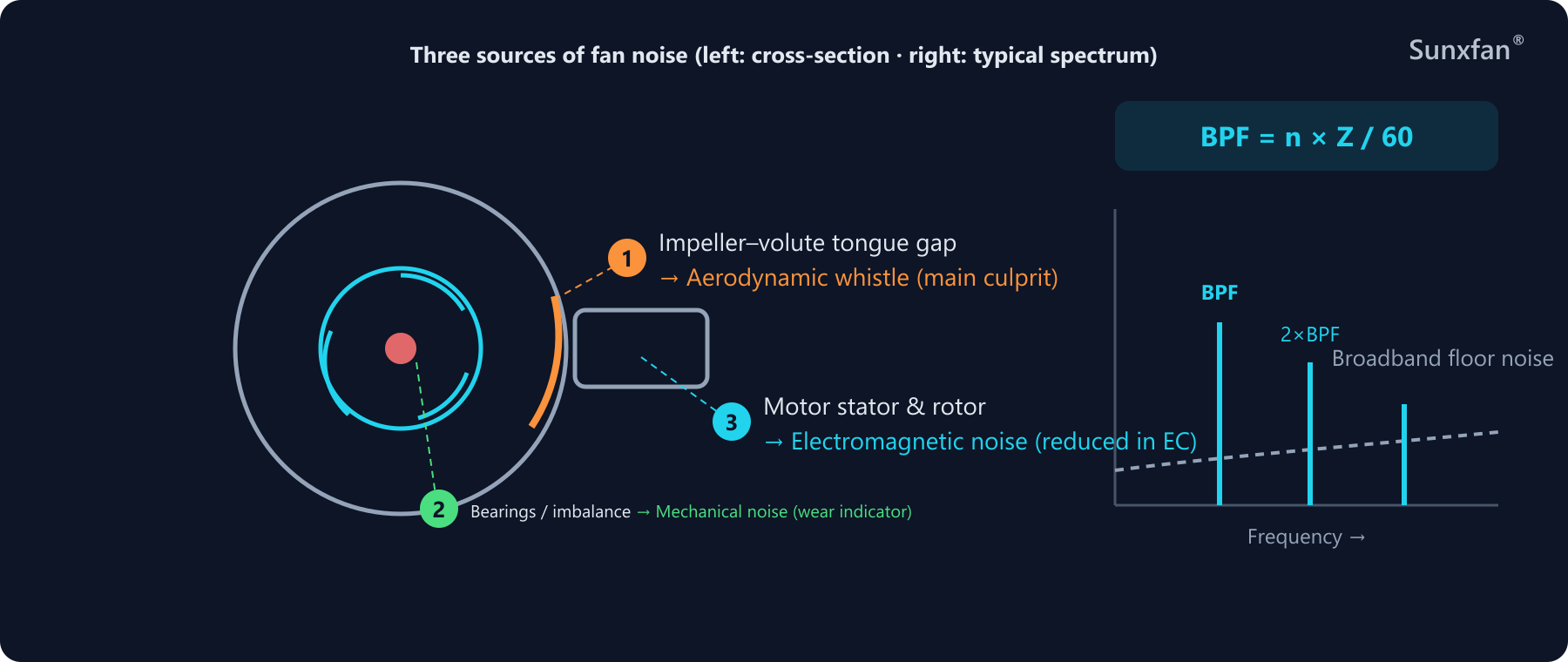
Figure 5 · Three sources: aerodynamic (BPF line spectrum + broadband turbulence), mechanical and electromagnetic; on the spectrum, BPF and its harmonics stand out the most
4. How Datasheet Noise Values Are Measured (and Why You Shouldn’t Take Them at Face Value)
4.1 Standard Test Conditions
Datasheet noise values are usually measured at rated voltage, full speed, in an anechoic (free) field, on the intake axis at 1 meter. Common test standards include:
- ISO 3744 / ISO 3745 (determination of sound power level)
- ISO 7779, JIS 8346 (noise of information technology equipment)
4.2 Why Everything Changes Once Installed
Datasheet figures are reference values. Inside real equipment, at least five factors rewrite them:
- System resistance shifts the operating point → away from rated duty, aerodynamic noise rises
- Ductwork geometry (bends, grilles, louvers) adds turbulence and resistance
- Structural resonance: fan vibration transmits into thin sheet metal and is amplified into a radiated “buzz”
- Multiple fans summing: the +3 dB-per-doubling effect
- Mounting method: cantilevered installs, uneven screw torque and missing vibration isolation all introduce vibration noise
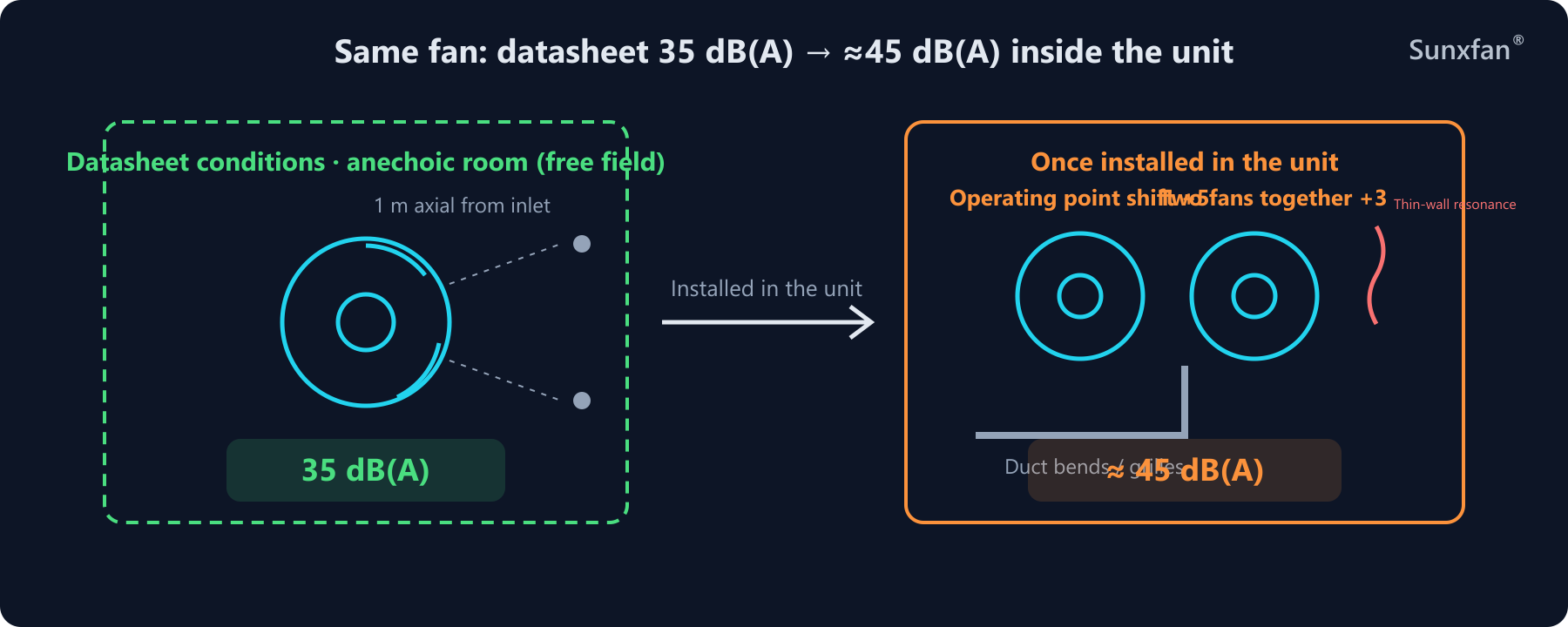
Figure 6 · A fan rated 35 dB(A) in free field can measure above 45 dB(A) once installed, after operating-point shift, resonance and multi-fan summation
5. Speed Is the Primary Lever on Noise
The fan affinity laws show just how powerful speed is:
| Parameter | Relation to speed n |
|---|---|
| Airflow Q | ∝ n |
| Total pressure P | ∝ n² |
| Shaft power W | ∝ n³ |
| Sound power (approx.) | ∝ n⁵ ~ n⁶ |
By the fifth-power law estimate: halving the speed cuts the sound power level by about 50 × log₁₀(2) ≈ 15 dB(A) — the theoretical origin of the widely quoted “halve the speed, drop 15 decibels” rule (in practice 10–15 dB, depending on duty and measurement conditions).
This law directly yields the golden rule of fan selection:
Given the required airflow, always prefer a larger-diameter, lower-speed fan. A large impeller at low speed and a small impeller at high speed can deliver the same airflow — but the latter’s sound power is far higher.
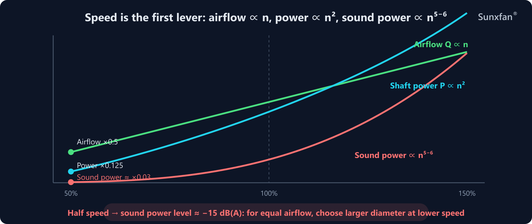
Figure 7 · Fan affinity laws: halving the speed means airflow ×0.5, power ×0.125 and a sound power level drop of about −15 dB(A)
6. Putting It into Practice: A System-Level Noise-Reduction Checklist
6.1 On the Selection Side (The Fan Itself)
- Size it adequately, not generously — 20% headroom rather than 50%. The price of oversizing is years of high speed and high noise
- For the same airflow, choose larger diameter at lower speed
- Prefer EC (electronically commutated) fans: smooth speed control, stepless speed reduction, low electromagnetic noise — one of the core reasons EC fans have been displacing AC fans in recent years
- Match the blade type to the duty point: backward-curved centrifugal (high efficiency, low noise — ideal for AHU and cleanroom duty), forward-curved (high airflow but comparatively noisy), axial (high flow, low pressure). The differences are compared in Axial vs Centrifugal Fans
6.2 On the System Side (Equipment Engineers)
| Measure | Principle | Key point |
|---|---|---|
| Enlarge intake/exhaust opening area and open-area ratio | Lower airflow resistance | High resistance → operating-point shift → noise rises |
| Straight duct runs, fewer bends | Pressure drop ∝ velocity² | Louver-style intakes add local losses |
| Keep the fan ≥5–10 mm from the enclosure wall | Avoid abrupt pressure changes | Noise from large-to-small transitions exceeds the reverse |
| Torque screws evenly to a specified value | Suppress vibration transmission | Uneven loading is the chief cause of resonance |
| Evaluate horizontal vs. vertical mounting | Vibration + airflow behavior | Vertical mounting usually gives steadier flow |
| Add vibration pads / acoustic foam | Absorb high-frequency vibration | Blocks the structure-borne path |
| Use guide vanes to direct the airflow | Smooth flow, lower resistance | Improves cooling efficiency and reduces noise at once |
| Choose series vs. parallel as needed | Series adds pressure, parallel adds airflow | Remember +3 dB per doubling in parallel |
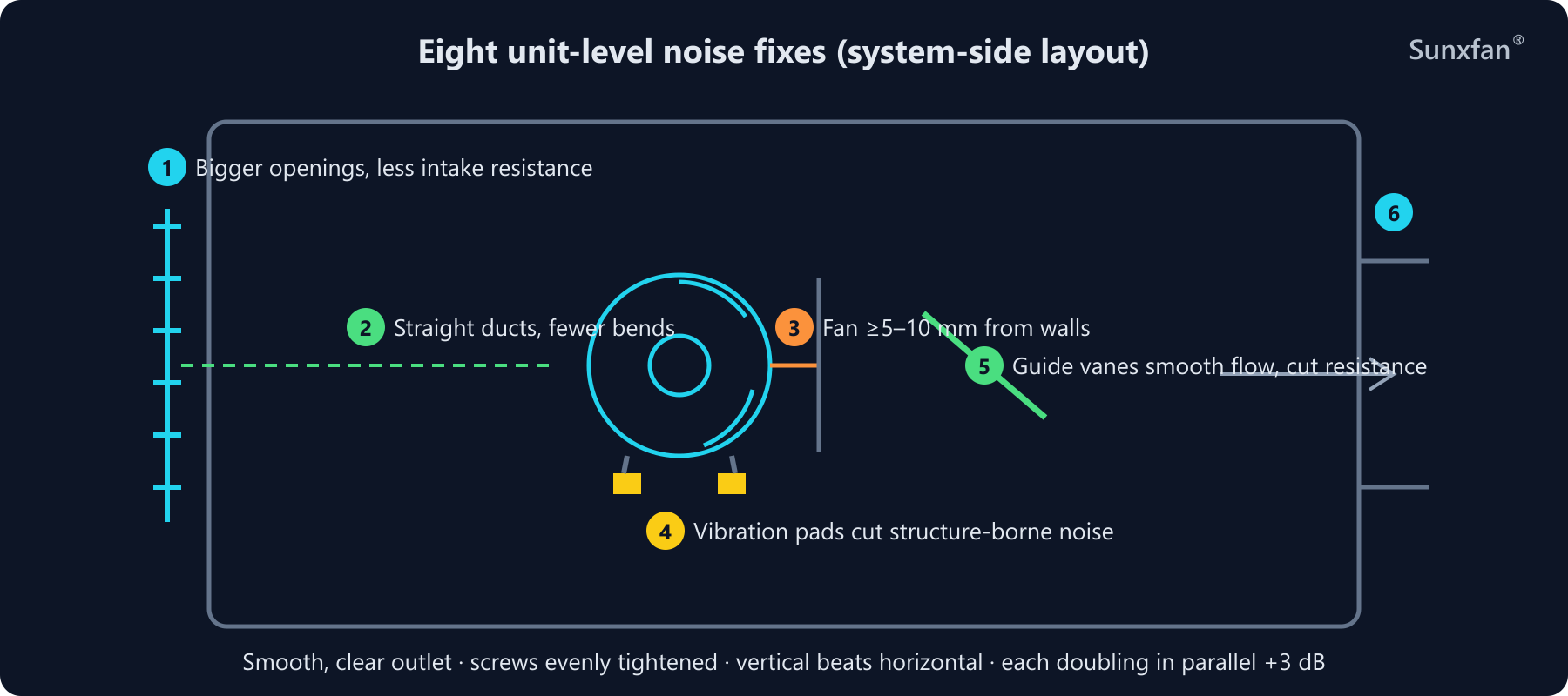
Figure 8 · Six key system-side noise-reduction points: open-area ratio, straight duct runs, wall clearance, vibration isolation, flow guidance and a smooth outlet
7. Back to Selection: Noise Profiles of the Main Fan Families
Drawing on the SUNXFAN product lines, here is a “noise-perspective” comparison for different applications:
| Series | Construction | Noise profile | Typical applications |
|---|---|---|---|
| BC backward-curved centrifugal series (bc133–bc310) | Backward-curved blades + EC motor | High efficiency → lower speed for the same airflow; broadband-dominant with no tonal whine — a “clean” spectrum | AHUs, data-center fan walls, cleanrooms |
| SF dual-inlet series (sf133–sf235) | Dual-inlet centrifugal | Symmetric dual-side intake — low vibration, smooth running; the mainstream choice for compact, low-noise range-hood-type duty | Range-hood blowers, ventilation equipment |
| DG single-inlet series (dg120–dg200) | Single-inlet centrifugal | Compact structure with ample room for scroll acoustic treatment | General ventilation, HVAC equipment |
| AF / AG axial series | Axial | High airflow at low static pressure; blade-tip speed is the noise key, and large-diameter low-speed designs cut noise significantly | Heat-pump outdoor units, condensers |
| Forward-curved single-inlet (RV applications) | Forward-curved centrifugal | High airflow per size, but densely spaced blades push BPF high — watch for high-frequency whine | RV air conditioners, mobile equipment |
One-sentence summary: the goal is not “pick the quietest fan” — it is “pick the fan that is quietest at your duty point”.
Conclusion
- The decibel is a logarithmic scale: doubling the energy adds only +3 dB, and doubling the number of fans adds only +3 dB
- dB(A) is the ear-corrected language of engineering; phon/sone are the precise language of psychoacoustics — when dBA values are close but one fan sounds worse, check sharpness and fluctuation strength
- Fan noise has three sources: aerodynamic (the main actor), mechanical (the degradation signal), electromagnetic (already subdued in the EC era)
- Datasheet noise is a free-field reference value — the system is the decisive variable
- The first lever for noise reduction is speed: larger diameter at lower speed is the golden rule; the second lever is system airflow resistance and mounting
Related Reading