
A fan catalogue is a contract with a set of assumptions, and the most frequently broken one is also the least visible: a free inlet and a free outlet. The moment a guard grille, a cooling coil, a plenum wall or an enclosure panel enters the impeller diameter in front of or behind the fan, the published P-Q curve stops describing the machine you installed. The flow does not simply fall by a fixed percentage that you could subtract from the rating — the shape of the curve changes, and it changes most at the airflow end you selected the fan for.
This matters more for axial fans than for centrifugal ones, because an axial impeller is sensitive to what the approaching air is already doing when it arrives. Plate blockage and inlet swirl both attack the same mechanism: the blade sees an angle of attack it was not designed for, the work per unit of air drops, and the fan converts less of its input power into useful static pressure. What follows is the engineering version of that story — mechanism, calculation, clearance rules, and citable numbers for the AS series EC axial fans, using the AS910A-E150A3-01 (25,000 m³/h, 300 Pa, 380-480 V AC three-phase EC) as the worked platform.
Quick Answer: What Blockage Does to a Fan Curve
Blockage adds two separate penalties, and conflating them is what makes installed airflow so hard to predict:
- System resistance — an obstruction reduces the open area, so the air must move faster through the remaining gap. This raises the system resistance curve. It is calculable, and every handbook covers it.
- Fan-curve degradation — the changed inlet and outlet flow field (swirl, non-uniform approach, reverse flow at the hub) reduces the pressure the fan can generate at a given flow. This is not in the catalogue, is not in the handbook, and is the reason a system that checked out on paper runs short on site.
The practical consequence: if you correct only the system curve for a blockage, you will over-predict the delivered airflow, because you have credited the fan with head it can no longer produce. Published rig measurements on an automotive axial fan show the degradation concentrated at medium-to-high flow — precisely the region where a 25,000 m³/h class fan earns its place.
Two Penalties, Not One
| Penalty | Physical cause | Predictable from the catalogue? | Where it bites |
|---|---|---|---|
| System resistance | Reduced open area → higher local velocity → higher friction and dynamic loss | Yes. Standard duct and grille loss calculation | All flows; scales with velocity squared |
| Fan-curve degradation | Distorted inlet/outlet field: swirl, vena contracta, hub recirculation, asymmetric approach | No. Must be measured or computed for the geometry | Medium-to-high flow — the rated end of the curve |
Design practice follows from the table. Reduce the first penalty by geometry, and treat the second as a safety margin you must have physical evidence for.
Mechanism 1 — Inlet Geometry: Bell Mouth Versus Square Edge
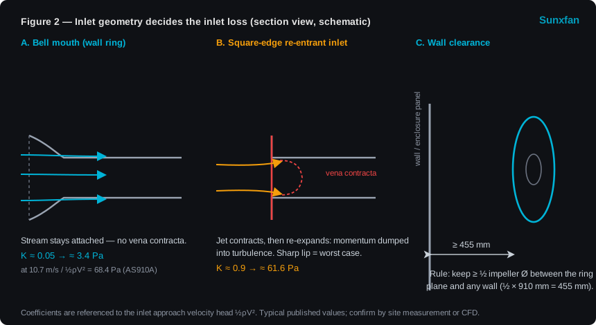
Figure 2 — The inlet lip decides whether the approach stream stays attached. A bell mouth holds the loss near 1/20 of the approach velocity head; a sharp re-entrant lip dumps about 0.9 of that head into turbulence.
An inlet without a rounded approach lip forces the stream to separate at the edge, contract to a vena contracta smaller than the opening, and then re-expand — dumping momentum into turbulence on the way. Standard values, both referenced to the inlet approach velocity head ½ρV²:
| Inlet type | Loss coefficient K | Loss at 10.7 m/s (½ρV² = 68.4 Pa) |
|---|---|---|
| Bell mouth (the AS series wall ring) | ≈ 0.05 | ≈ 3.4 Pa |
| Square-edge re-entrant | ≈ 0.9 | ≈ 61.6 Pa |
At the AS910A-E150A3-01 rating point the ring-plane velocity is 10.7 m/s, so the inlet velocity head is 68.4 Pa at ρ = 1.2 kg/m³. The difference between the two geometry choices is therefore about 58 Pa — roughly 19% of the fan’s entire 300 Pa static-pressure budget, spent on nothing more than the shape of the inlet lip. That is the quantitative argument for buying the integrated wall ring rather than bolting a plain plate to the opening.
Wall proximity is the other half of inlet geometry. Keep at least half an impeller diameter between the ring plane and any wall, floor, ceiling or panel — 455 mm for the 910 mm AS910A. Closer than that, the approach velocity is higher along the bottom of the opening than the top, and the resulting velocity gradient rolls up into a swirl.
Mechanism 2 — Inlet Swirl: Direction Decides the Sign, Efficiency Falls Either Way
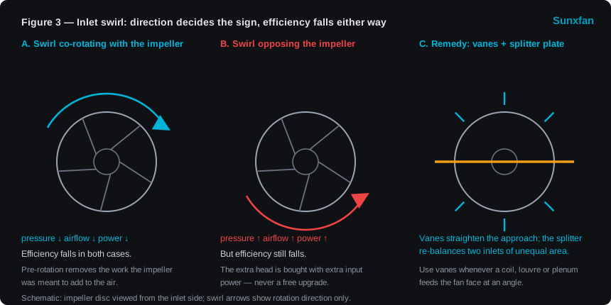
Figure 3 — Swirl direction sets the sign of the pressure, airflow and power change, but the efficiency loss is common to both cases.
Swirl arriving at an axial impeller is not always bad news for the headline numbers:
| Inlet condition | Static pressure | Airflow | Power | Efficiency |
|---|---|---|---|---|
| Swirl co-rotating with the impeller | ↓ | ↓ | ↓ | ↓ |
| Swirl opposing the impeller | ↑ | ↑ | ↑ | ↓ |
| Uniform, axial approach | reference | reference | reference | reference |
The counter-rotating case is the trap. Pressure, airflow and power all rise, which looks like a free upgrade, but the efficiency denominator rises faster than the useful output — the fan is now working the air harder for each unit of input. The co-rotating case is the one usually encountered in practice: pre-rotation from an upstream coil bank, an angled louver, or an asymmetric plenum robs the impeller of the work it was meant to add.
Two constructive fixes, both from the same design family as the wall ring:
- Guide vanes in the approach duct straighten the stream before it reaches the blades. Use them whenever a coil, louver or plenum feeds the fan face at an angle.
- A splitter plate breaks the swirl that forms when two inlets of unequal area feed the same fan face. The unequal openings create the pressure imbalance, and the imbalance creates the rotation.
Mechanism 3 — Downstream Blockage: Guard Grilles, Coils and Plenum Walls
Outlet blockage behaves differently from inlet blockage, and the rig evidence is unambiguous. In controlled measurements on an automotive axial fan — hot-wire anemometry plus laser Doppler velocimetry, with the blockage plate moved from 65 mm to 125 mm behind the trailing edge and the measurement plane 3 mm behind the trailing edge at 15 mm radial spacing — three findings matter to any axial fan selection:
- The curve degrades, and degrades selectively. Comparing the blocked curves to the free-fan curve, the loss is small at low flow and grows sharply through the medium-to-high flow range. The blocked fan still holds pressure at low flow; it cannot hold airflow at high flow.
- Reverse flow appears at the hub. Blocked, the axial velocity near the hub turns negative — the inner part of the annulus starts recirculating instead of delivering.
- The flow turns outward. Radial velocity increases while axial velocity decreases, which is another way of saying the volumetric flow falls even though the impeller is still turning at the same speed.
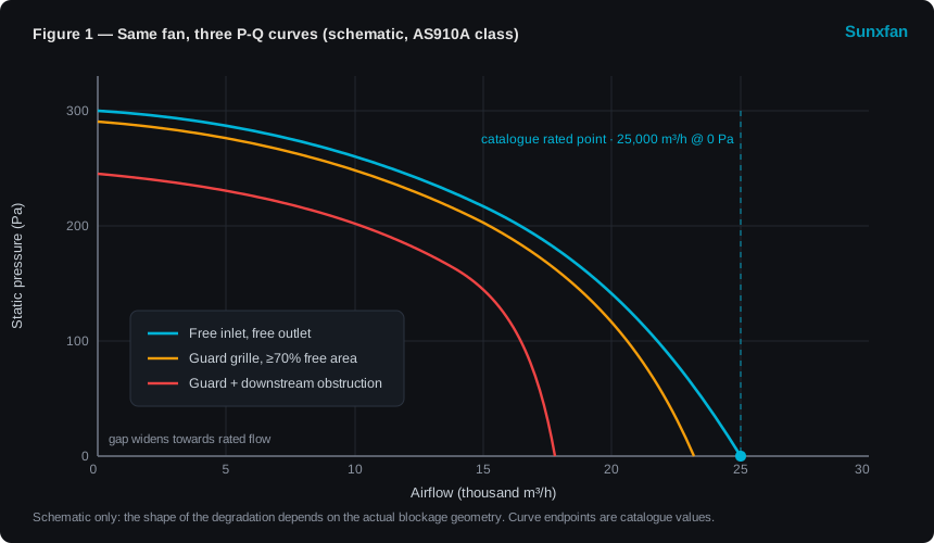
Figure 1 — The same fan, three curves. Catalogue (free inlet and outlet), a guard grille with high free area, and a guard behind a downstream obstruction. The gap widens towards the rated airflow — the sector the system was sized on.
The engineering consequence is a design rule that costs nothing to follow: the hub is where blockage bites first. Do not place a coil header, a structural beam, a plenum step or an access panel directly opposite the impeller hub. If the geometry cannot be changed, the fan must be selected with explicit margin, not with the catalogue number.
For the AS series this is the whole reason the guard is integrated into the ring rather than spaced off it — the closest possible position, in the plane of the ring. When the setback is essentially zero, the governing variable is no longer distance but free area, which is why the guard is specified by open area rather than by standoff.
Quantifying Blockage: The Three-Line Method
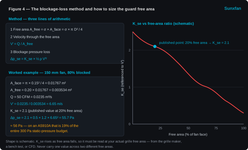
Figure 4 — The whole method in three lines, the standard worked example, and a reminder that K_se is a function of free area rather than a constant.
Blockage loss can be quantified with a single coefficient, referenced to the velocity through the free area rather than to the fan face:
Step 1 — Free area A_free = σ × A_face = σ × π D² / 4, where σ is the free-area ratio of the guard or grille.
Step 2 — Velocity through the free area V′ = Q / A_free
Step 3 — Blockage pressure loss Δp_se = K_se × ½ ρ V′²
Worked example (published data). A 150 mm fan with 80% of its opening blocked, so σ = 0.20, moving 50 CFM:
| Quantity | Value |
|---|---|
| Face area | A_face = π × 0.15² / 4 = 0.01767 m² |
| Free area | A_free = 0.20 × 0.01767 = 0.003534 m² |
| Flow | Q = 50 CFM = 0.0235 m³/s |
| Velocity through free area | V′ = 0.0235 / 0.003534 = 6.65 m/s |
| Loss coefficient at 20% free area | K_se = 2.1 |
| Blockage loss at ρ = 1.2 kg/m³ | Δp_se = 2.1 × 0.5 × 1.2 × 6.65² = 55.7 ≈ 56 Pa |
Read that number against the fan. 56 Pa is a real pressure that has to come out of the fan’s budget before any system duct, coil or filter is paid for. On an AS910A-E150A3-01 with 300 Pa of static pressure, a 56 Pa blockage penalty consumes 19% of the entire budget:
| Blockage loss | Share of the AS910A 300 Pa static-pressure budget |
|---|---|
| 10 Pa | 3.3% |
| 30 Pa | 10% |
| 56 Pa | 18.7% |
| 62 Pa (square-edge re-entrant inlet) | 20.7% |
One caveat decides whether the method is trustworthy. K_se is not a constant. It rises as the free area falls — a fully blocked opening is an infinite loss — so a value read at 20% free area must not be carried across to a 70% free-area grille. Obtain K_se for the actual free area from the grille manufacturer, a bench test, or CFD. The method above then converts it into a pressure that you can place directly on the system-resistance curve, in the same units as every other loss.
The Dimensionless View: Why Curves Collapse
Blocked-fan measurements are only comparable to a catalogue when both are expressed as dimensionless coefficients rather than in m³/h and Pa. Using n for rotational speed (rev/s) and D for impeller diameter (m):
- Flow coefficient: φ = Q / (n · D³)
- Pressure coefficient: ψ = 2 Δp_s / (ρ · n² · D²)
Different textbooks place constant factors (π², 2) differently, so the absolute values shift — but the shape does not. For the AS910A-E150A3-01, taking the catalogue speed of 930 r/min (15.5 rev/s) and D = 0.91 m as the reference, the two catalogue endpoints map to:
| Catalogue endpoint | φ | ψ |
|---|---|---|
| Shut-off (0 m³/h at 300 Pa) | 0 | ≈ 2.51 |
| Free delivery (25,000 m³/h at 0 Pa) | ≈ 0.59 | 0 |
Plot any blocked measurement on these same axes and the blockage shows up as the points falling below the catalogue curve — and, as the rig data showed, falling furthest at high φ. That is the comparison that tells you whether you are looking at a fan problem or a system problem.
Sizing the AS Series for a Real Installation
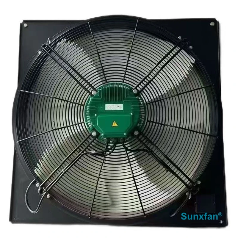
The AS series — high-airflow EC axial fans with a wall ring and guard integrated in the ring, 380-480 V AC three-phase, IP55, −40 °C to +65 °C.
All four models share the same pressure ceiling and the same control interface (0-10V/PWM and Modbus RTU over RS-485), so the selection step is mostly about fit, noise and face velocity rather than about pressure:
| Model | Impeller class | Rated airflow | Speed | Power | Noise | Face velocity at ring plane |
|---|---|---|---|---|---|---|
| AS760A-E137A3-01 | 760 mm | 16,500 m³/h | 950 r/min | 1,100 W | 69 dB(A) | 10.1 m/s |
| AS860A-E150A3-01 | 860 mm | 24,000 m³/h | 920 r/min | 1,800 W | 72 dB(A) | 11.5 m/s |
| AS910A-E150A3-01 | 910 mm | 25,000 m³/h | 930 r/min | 1,800 W | 73 dB(A) | 10.7 m/s |
| AS960A-E150B3-01 | 960 mm | 29,000 m³/h | 915 r/min | 3,200 W | 75 dB(A) | 11.1 m/s |
Because the family sits in a narrow 10-11.5 m/s band at the ring plane, the same blockage arithmetic applies across it. Face velocity is the number to carry into the guard calculation, because the guard is the blockage: every percentage point of free area you give up raises the local velocity at the grille by the same percentage.
| Guard free area σ | V′ through the guard, AS910A at 25,000 m³/h | Consequence |
|---|---|---|
| 100% (no guard) | 10.7 m/s | Reference face velocity |
| 90% | 11.9 m/s | Negligible on a well-formed grille |
| 80% | 13.4 m/s | Still modest — the comfortable design band |
| 70% | 15.3 m/s | Practical lower limit for a working grille |
| 50% | 21.4 m/s | Leaks significant pressure; re-check the whole system |
| 20% | 53.4 m/s | Reference point of the published example — far outside the fan capability at this size |
The band from 80% to 70% free area is where a guard grille belongs: open enough that the loss stays a small fraction of 300 Pa, closed enough to do the safety job it was fitted for. Below 70%, the grille is no longer an accessory — it is a system component that has to be paid for out of the fan’s pressure budget and declared in the selection.
Installation Clearance Rules
These are the rules that carry directly into a drawing package. Every value in the right-hand column is for the AS910A-E150A3-01 (D = 910 mm).
| Item | Rule | Value for a 910 mm fan |
|---|---|---|
| Inlet to any wall, floor, ceiling or panel | ≥ ½ impeller diameter | ≥ 455 mm |
| Inlet ducted at the fan face | Bell mouth (wall ring) mandatory; avoid a square-edged re-entrant inlet | K ≈ 0.05 versus 0.9 |
| First obstruction downstream | ~1 impeller diameter where the duct allows; under ½ Ø is a design fault | ~910 mm target, 455 mm floor |
| Guard grille free area | ≥ 70% of the ring area | V′ ≤ 15.3 m/s at 25,000 m³/h |
| Inlet fed by two openings of unequal area | Add a splitter plate | Prevents the swirl that unequal areas create |
| Any obstruction opposite the hub | Avoid. Blockage induces reverse flow at the hub first | Keep coil headers, beams and access panels clear |
| Two fans side by side or stacked | Allow the clearance to the shared wall for both units | Rule applies per fan, not per bank |
Commissioning: Verify the Operating Point, Do Not Assume It
A clearance drawing gets the installation right on paper; commissioning proves it in the plant. Three checks close the loop:
- Measure the static pressure across the fan and the velocity through the guard free area. A differential pressure reading at the fan, compared to the corrected catalogue curve, tells you immediately whether the installation is delivering the rating.
- If airflow is short, apply the fan laws before raising speed. Q scales with speed, static pressure with its square, shaft power with its cube:
| Speed | Airflow | Static pressure | Shaft power |
|---|---|---|---|
| 100% | 100% | 100% | 100% |
| 105% | 105% | 110% | 116% |
| 110% | 110% | 121% | 133% |
| 120% | 120% | 144% | 173% |
For the AS910A-E150A3-01 at 1,800 W, a 10% speed increase asks for about 2,396 W of shaft power. If the shortfall was caused by blockage rather than by under-sizing, driving speed up fights the symptom with a disproportionate power and noise cost — and eventually hits the motor thermal limit instead of restoring airflow.
- Read the drive back over Modbus RTU. The same two-wire RS-485 that runs the plant carries setpoint out and speed, current and status back. Logging current against speed command makes a blocked or fouled installation visible before it becomes a thermal event on the equipment being cooled: a fan that needs more current than it did at commissioning, at the same setpoint, has lost free area to dust, or gained a downstream obstruction. This also converts maintenance from calendar-based to condition-based.
Selection Checklist
- Fix the duty: airflow at the actual system resistance, not at 0 Pa.
- Measure the available inlet envelope. If it is less than half an impeller diameter in any direction, change the geometry or re-select a smaller fan.
- Confirm the inlet has a bell-mouth approach (wall ring). If not, add about 58 Pa to the loss budget at this size class, or fit a wall ring.
- Confirm the approach is axial and uniform. Coil banks, louvers and unequal twin inlets all need guide vanes or a splitter plate.
- Take the guard grille free area from the actual grille, not from the drawing symbol. Design for ≥ 70%.
- Compute V′ = Q / A_free and place Δp_se = K_se × ½ρV′² on the system-resistance curve alongside filters, coils and louvres.
- Check the first downstream obstruction against one impeller diameter; anything under half a diameter is a defect to be corrected in the layout.
- Re-read the corrected P-Q curve at the resulting system resistance. If the operating point has drifted below the rating by more than the project tolerance, step up a model within the AS family rather than raising speed.
- Size for the blockage you expect at end of life (dust-loaded filters, fouled coils), not for the day-one installation.
- Decide the control strategy: fixed setpoint, temperature-driven via Modbus, or a scheduled duty. Blocked systems are far easier to manage when the fan reports its own current.
Bottom Line
An axial fan catalogue curve is a free-inlet, free-outlet curve, and a real installation is never that. Two things then happen at once: system resistance rises, and the fan generates less pressure at high flow. The second is invisible in every handbook and is where installed airflow disappears.
For the AS series, four numbers settle most arguments: half an impeller diameter (455 mm) to any inlet wall, about one impeller diameter (910 mm) to the first downstream obstruction, ≥ 70% guard free area (V′ ≤ 15.3 m/s at 25,000 m³/h), and an inlet lip worth 3.4 Pa against 61.6 Pa for a square edge. Spend the small money on the ring and the guard, place the loss on the system curve as Δp_se = K_se × ½ρV′², and commission with a differential pressure reading instead of an assumption.
For a unit-by-unit comparison across the family, see the AS Axial-Fan Integrated Guard Ring series or the AS910A-E150A3-01 product page. If your duty is dominated by static pressure rather than by bulk airflow, compare against the centrifugal fan selection guide before committing to an axial fan.