
Fifteen years ago the drawing showed one signal wire for speed control: the controller produced a 0-10V level or a PWM duty cycle, it went into the fan connector, 10% meant stop, 90% meant full speed, and everything in between was linear. Open the electrical schedule for a new project today and that same wire has sometimes become a Modbus twisted pair, sometimes a CAN differential pair — while on a great many machines still in production it has not changed at all.
So the person drawing the schematic gets asked: what should this wire be today?
The stock answer is “0-10V is cheap, Modbus is universal, CAN is advanced”. That answer was mostly right ten years ago and is not good enough now, because it puts four different tiers of things on the same scale.
The short answer
- One fan, or two or three, and you only need to set the speed: 0-10V or PWM, whichever your controller can output.
- You have a PLC and need speed, current, temperature and fault codes back: Modbus RTU over RS485.
- Several fans must stay in sync, faults must be graded, or you are on a platform above 400 VDC: CAN FD.
- Automotive LIN projects: not available as a standard part; it is an OEM custom.
Everything else, and the cost of each choice, is laid out below.
1. Six interfaces, four tiers
Arguments about this rarely conclude, usually because a voltage level and a network are being treated as the same kind of object. Start with where each one actually sits.
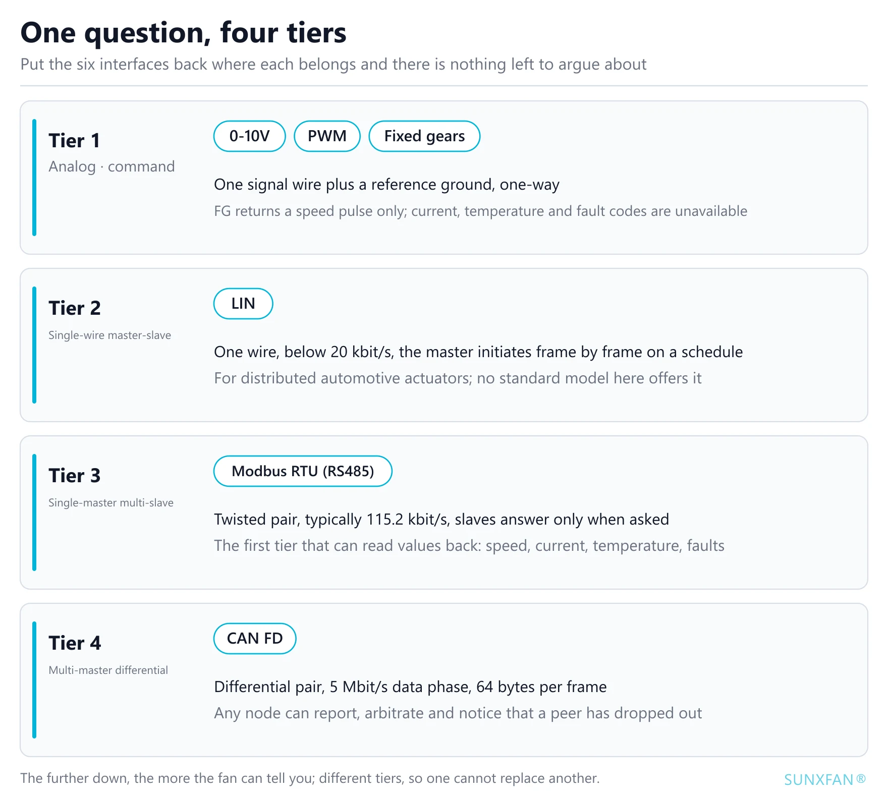
0-10V is a voltage
No address, no frame header, no checksum. The entire “protocol” on the fan side is a divider network and one A/D sample, carrying a scalar: how fast, right now. A broken wire reads 0 V, which is a command to stop — the failure mode you have to handle in advance.
The only thing that comes back is FG: one speed pulse train, a fixed number of square waves per revolution, which the controller turns into actual speed with an input capture. It gives you speed. It cannot give you current, temperature or fault codes.
PWM is a duty cycle
Still a scalar, with the magnitude encoded as a time ratio. The advantage is immunity: interference changes a voltage level far more easily than it changes the proportion of a period spent high, so long cable runs are more forgiving than with 0-10V. The cost is a frequency reference — controller and fan must agree on the frequency window, or the reading drifts.
Fixed gears are not the cheap option, they are the calibration-free one
55 models in our catalogue offer 3 speeds and 26 offer 4. These are, in essence, a handful of preset duty cycles selected by digital inputs or a few discrete levels. On an air handling unit that only ever needs low, medium or high, fixed gears are less work than stepless control: no calibration, no analog output module in the PLC, and a miswire will not destroy the fan.
LIN is an automotive single-wire master-slave bus
The first three are analog. The bus story starts at LIN — Local Interconnect Network, a low-cost scheme designed specifically for small distributed actuators in vehicles. It grew out of the same need as CAN, with a completely different intent.
Four things define it:
- One signal wire plus ground, 12 V logic, 20 kbit/s maximum — two orders of magnitude below CAN.
- Strictly master-slave: one master node initiates frame by frame according to a pre-arranged schedule, and slaves can only answer. There is no arbitration and no possibility of two nodes fighting over the wire.
- A fixed frame: break, sync field, protected identifier, 1-8 data bytes, checksum. The specification is usually quoted at up to 16 slaves; engineering practice keeps it to 12 or fewer.
- Very low cost: modern motor control ICs often integrate the LIN transceiver, so the marginal cost over a purely analog design is one wire and one channel on the master side.
Whether it is worth using comes down to two preconditions: has the control law already moved into the fan itself (you only need to converse if the fan has something to compute), and does the vehicle need fan-level data for diagnostics and calibration. With both true, LIN pays off. With only one, analog is cheaper.
Why we offer no LIN models at all. On industrial equipment the bus is already owned by the PLC or a gateway, there are typically one to a few fans, and nothing requires them to sit on an automotive harness being polled on a schedule. At the same low-cost tier, Modbus RTU offers a higher data rate, mature configuration tooling and an existing diagnostics ecosystem. So of the 121 models in the catalogue, the number supporting LIN is zero. The interface follows the architecture of the system you are building, not the buzzword of an industry.
Modbus RTU is a single-master multi-slave bus
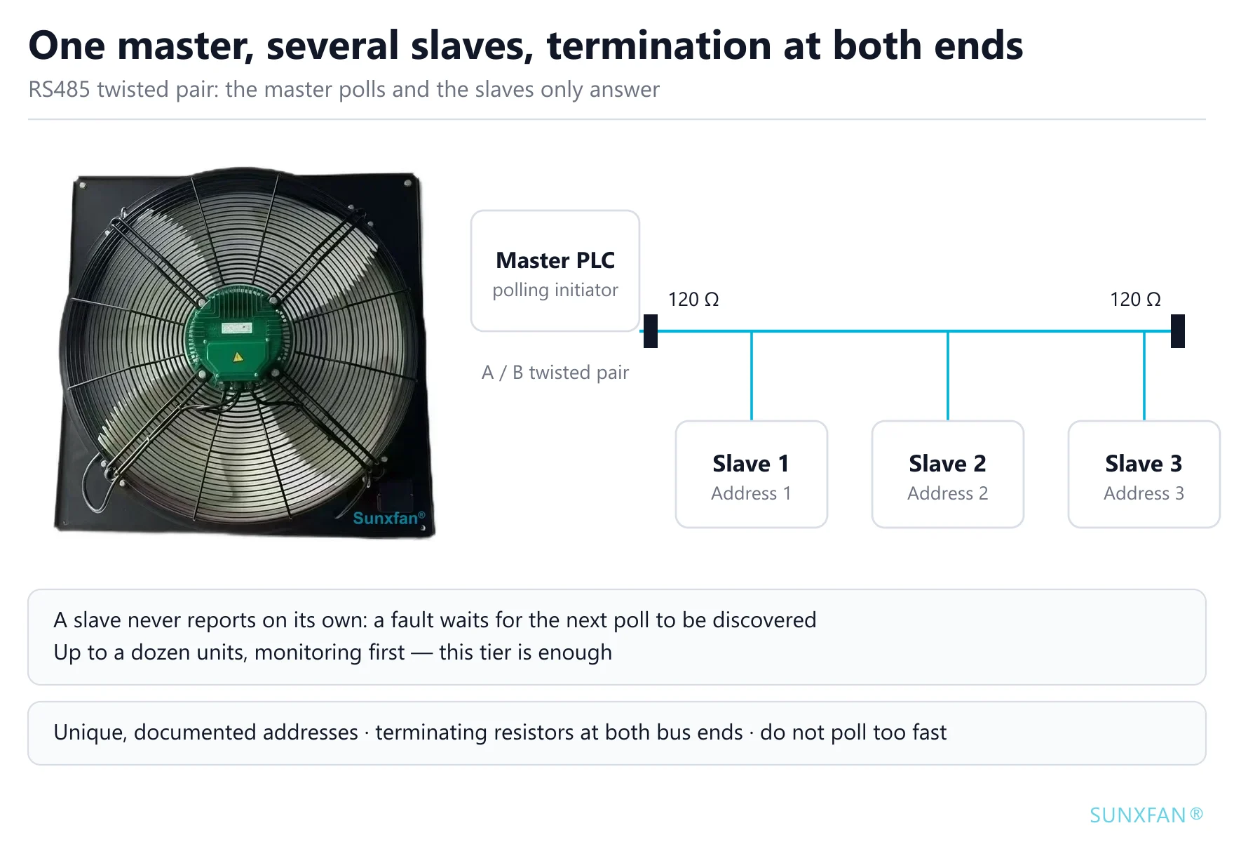
RS485 twisted pair, one master and several slaves, and slaves answer only when asked. Typically 115.2 kbit/s, with addresses that must be assigned by hand and terminating resistors that must be fitted. It is the first tier that makes “read the value back” possible: how fast it is turning, how much current it draws, whether it has a fault.
It is worth separating it from LIN. Both are master-slave, but LIN is single-wire, slow and aimed at chip-level cost, while Modbus RTU is differential twisted pair, two orders of magnitude faster and aimed at cabinets and production lines. What industrial engineers mean by “put it on the bus” is almost always the latter.
CAN FD is a different responsibility model
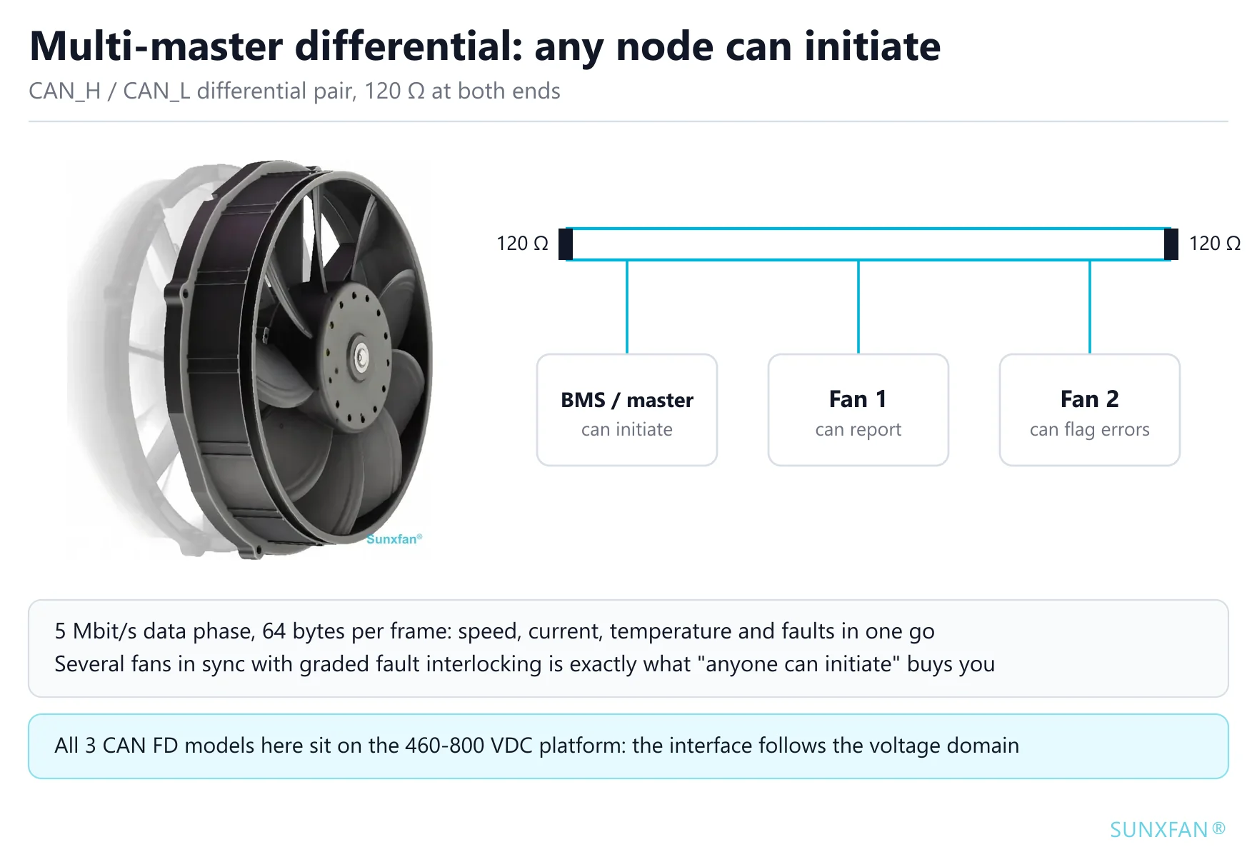
It is not a faster Modbus. Two-wire differential, multi-master arbitration, hardware error detection and retransmission, a data phase up to 5 Mbit/s and 64 bytes per frame (Classic CAN stops at 8). Any node can report spontaneously, take part in arbitration and tell that a peer has dropped off. That is not more communication capability; it is a different boundary of responsibility — anyone may initiate, and nobody waits to be polled.
2. The real dividing line: does this fan need to talk?
Translate the six interfaces into interaction models and there are only four:
| Interaction model | Interface | What you can do | What you cannot read |
|---|---|---|---|
| Command | 0-10V, PWM, fixed gears | Tell it how fast; FG returns a speed pulse | Current, temperature, fault codes, firmware version (speed is available via FG) |
| Session (single wire) | LIN | The master asks frame by frame on a schedule, the slave answers | Spontaneous reporting; node count limited by the schedule |
| Session (twisted pair) | Modbus RTU | Ask one question, get one answer, and you may follow up | Spontaneous reporting — a slave never speaks first |
| Negotiation | CAN FD | Anyone can initiate, broadcast, detect errors and notice a peer dropping out | — |
The real question was never “which interface is better”. It is these two:
- Do you need to know what this fan is doing, or only that it is turning? That sets the bandwidth requirement.
- Does the final thermal safety decision live inside the fan, or inside the controller? That sets the boundary of responsibility.
The interface is the physical form of that boundary. Every “optimal choice” below is derived from those two answers.
One caveat worth stating plainly: on analog models the only thing that comes back is the FG speed pulse. To read current, temperature, fault codes or firmware version you need a model with Modbus or CAN FD. Clamping a current transformer or a cabinet temperature probe onto a purely analog model is a valid approach, but that is your own measurement chain, not something the fan provides.
3. The six interfaces, one at a time
0-10V: least work, most exposed to cable resistance and range
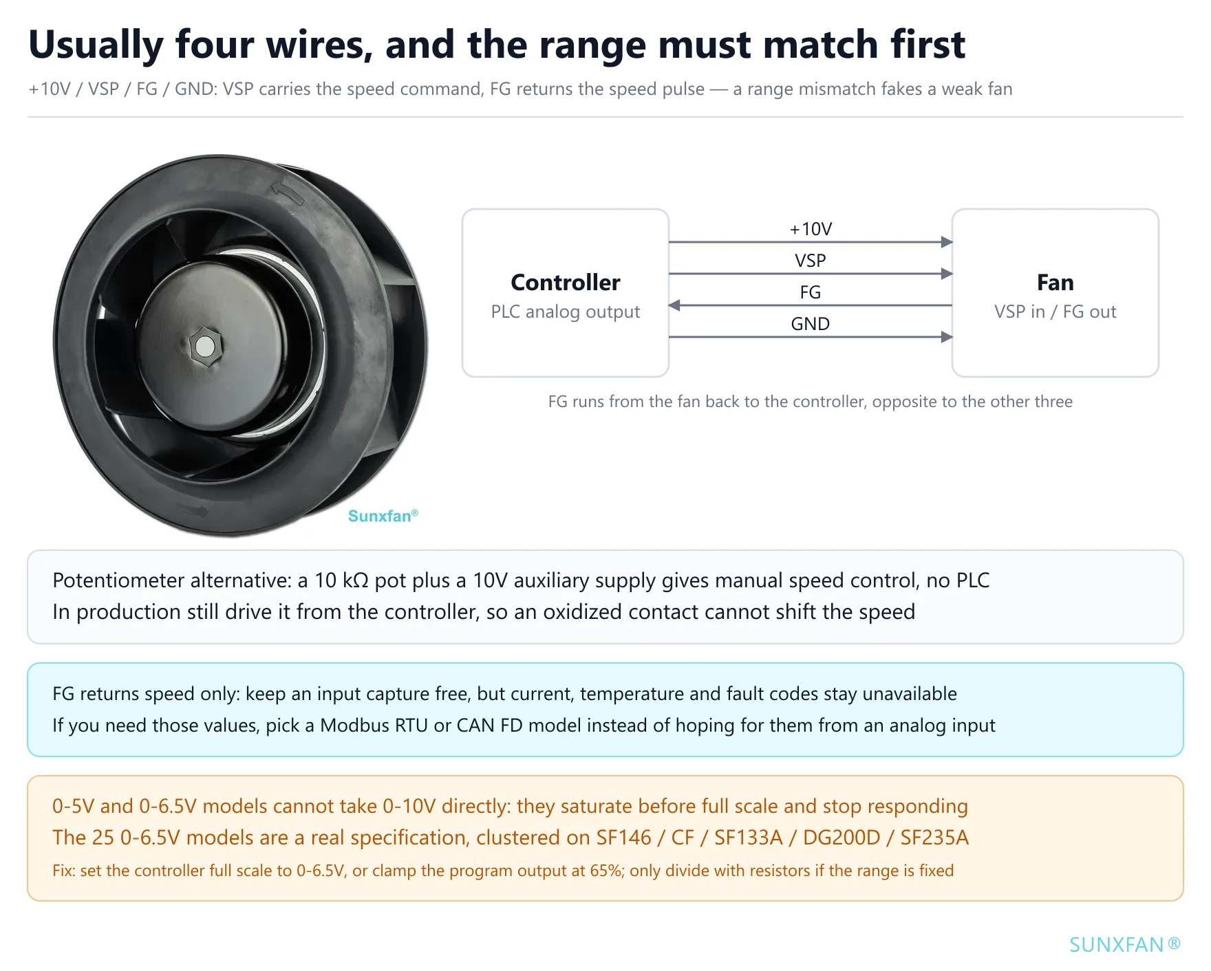
Wiring first. The usual arrangement is four wires: +10V, VSP, FG and GND. VSP is the speed command input and accepts either a 0-10V DC level or a PWM duty cycle; FG is the speed feedback pulse, running opposite to the other three, so the controller needs a spare input capture channel; GND is the signal reference and must come from the fan’s signal ground.
Once it is wired, two hazards show up.
The range has to match. 107 models in our catalogue support 0-10V/PWM; another 24 are 0-5V range and 25 are 0-6.5V. Neither group is a data-entry error: the 25 0-6.5V models cluster by control platform — SF146 (12, across SF146A, SF146C and SF146D), the CF duct fans (7), SF133A (3), DG200D (2) and SF235A (1). That is calibration by platform, not a typo.
Connect 0-10V straight in and the speed stops rising before the command reaches full scale: a 0-5V model tops out at 50%, a 0-6.5V model at 65%, and beyond that more signal changes nothing. It reads as “the fan has no power” rather than “the wiring is wrong”, and gets misdiagnosed as an undersized selection.
To make it work, in this order:
- Limit at the controller (preferred): if the analog output supports a custom full scale, set it to 0-6.5V; if it only offers fixed ranges (0-5V / 0-10V), clamp the output ceiling at 65% in the program. No extra hardware, linearity preserved, at the cost of some resolution.
- Divide the signal (fallback): a series and a shunt resistor scale 0-10V down to 0-6.5V at a ratio of 0.65 — for example 3.5 kΩ in series and 6.5 kΩ to ground. The source impedance at the divider node rises to the order of 2 kΩ, which is far more prone to picking up noise on long runs and in electrically noisy environments; use it only where the controller range cannot be changed, and measure the resulting speed curve afterwards.
- Do not do this: feed 10 V in and leave it. If either the clamp or the record of it is missing, the next person opens the output up and the speed stops rising again.
Whichever route you take, read the absolute maximum input voltage in the datasheet first. If it says 0-10V is allowed and the unit is merely calibrated at 0-6.5V, the first two options are both safe. If 6.5V is itself the upper limit, only option 2 stays inside it.
Treat long runs as analog. A high-impedance input draws no current, but the longer the cable the more interference it couples. Route it away from power cabling; beyond a few metres use shielded twisted pair with the shield grounded at one end. The reference ground must come from the fan’s signal ground, not from the cabinet’s power ground — the potential difference between the two adds directly to the command.
One practical benefit: because the input is high impedance, a 10 kΩ potentiometer and a 10V auxiliary supply give you manual stepless speed control with no controller at all. It is the fastest path during prototype bring-up and field troubleshooting. If the goal is only to break stepless control into a few fixed steps, that is a job for the controller side, not for the fan.
PWM: better immunity, at the price of dead bands at both ends
The usable PWM range is usually not 0-100% duty cycle. Both ends are normally reserved as dead bands, 10-90% being common, and inside a dead band the fan is not “very slow” but stopped or at full speed — the definition varies by model. Check the datasheet for the specific model; do not extrapolate from experience.
The frequency window works the same way. The PWM frequency your controller produces must fall inside the range given in the fan datasheet, otherwise the internal filter misreads the duty cycle and the speed drifts as the frequency changes.
PWM is a one-way downstream command. Some vendors return fault information by pulling the same wire low, but that needs dedicated design on the fan side and our analog models do not offer it. If you need diagnostics, use a bus or add your own measurement.
Fixed gears: where a few airflow steps suffice, they are the optimum
Make-up air units, dehumidifiers, simple in-cabinet circulation — airflow only ever needs low, medium or high. Going stepless there costs an analog output on the controller, a calibration session and an extra wiring diagram, and buys continuous adjustment that nobody uses.
We offer 3-speed on 55 models and 4-speed on 26. The wiring is a few digital inputs, and the cost is explicit: no smooth transition between steps, and an audible speed jump at each switch.
LIN: worth considering only when the automotive harness already exists
If your project is a vehicle harness to begin with, or the OEM has already put grilles, seats and pumps on LIN, that is a different set of preconditions. Then three things matter:
- Somebody has to be the master. LIN has no multi-master, the schedule must be transmitted by the master node, and if the master does not implement it the bus is dead.
- Diagnostic capability is limited. Speed, temperature and fault codes are readable, but the data rate makes refresh slow and unsuitable for millisecond-level interlocking.
- The failure behaviour has to be written into the protocol. Whether a communication loss triggers a protection mode or holds the current state is defined between the OEM and the supplier, not by the LIN specification — exactly like a lost 0-10V signal, it has to be confirmed item by item.
Industrial equipment does not choose it, for the reason given in the first section: Modbus RTU is a better fit at the same cost tier. If you genuinely need LIN, treat it as a custom project rather than looking for it in a standard catalogue.
Modbus RTU: the lowest rung that can read values back
If the requirement is “show me on the HMI how fast this fan is turning and whether it has an alarm”, Modbus RTU is the best value tier. 24 models in our catalogue support it, concentrated in the AS series EC axial fans (such as AS910A-E150A3-01, 380-480 VAC, 25,000 m³/h, 1800 W) and the backward-curved BC series (such as BC250A-E092D3-02, 230 VAC, 1420 m³/h, 160 W).
Three essentials: addresses must be unique and documented, terminating resistors must be fitted at both ends of the bus, and the polling interval must not be set too short — slaves are answer-only, so the more impatient the master, the less time is left for every other slave. Up to a dozen or so units, monitoring first, no millisecond interlocking: it is enough.
The limitation needs stating too: a slave never reports on its own. A fault is discovered only when the next poll asks. If thermal safety demands “if the fan stops, we must know immediately”, then the Modbus polling interval is your detection delay.
CAN FD: built for multi-fan coordination and graded faults
Only 3 models in our catalogue support it, all on the 460-800 VDC high-voltage platform: AG200A-D092BA-01, AG305A-D092BA-Y1 and AG400A-D092BA-02, all in the 800VDC axial series. That is not a coincidence; it is what happens when the interface follows the voltage domain.
In a high-voltage domain a kW-class fan is no longer a ventilation accessory but a primary actuator in the thermal management loop, competing with compressors, pumps and valves for cooling capacity. What that situation needs is not faster communication but three capabilities only a bus provides: multi-node coordination, graded faults (undervoltage, overtemperature and locked rotor mapping to derating, limp mode or shutdown), and interlocking on the same network as the other high-voltage equipment.
CAN FD support is not free: 120 Ω termination, branch-length limits and a matching common mode range all have to be designed in at system level, not added during commissioning.
4. How the interfaces are distributed across our 121 models
Selection advice that never lands on your own catalogue is just general education. Here is the count across the 121 models on this site (2026-11 data):
| Speed control interface | Models | Share |
|---|---|---|
| 0-10V / PWM | 107 | 88% |
| 3-speed fixed gears | 55 | 45% |
| 4-speed fixed gears | 26 | 21% |
| 0-6.5V analog | 25 | 21% |
| Modbus RTU (RS485) | 24 | 20% |
| 0-5V analog | 24 | 20% |
| CAN 2.0 / CAN FD | 3 | 2% |
| LIN | 0 | 0% |
Another 95 models (79%) offer two or more interfaces at once, which is to say the choice is often not either/or but two channels on the same fan. CF160-2000CFM-01, for instance, supports 0-10V/PWM, 4-speed fixed gears and Modbus RTU together, so you can bring a line up on analog and add the bus for remote monitoring later.
By motor type the 121 models split into 93 EC, 21 DC and 7 AC. Analog control is standard on EC and DC models; AC models are mostly fixed-speed and need no speed control interface at all. Browse the range by category: axial fans, backward-curved, rack-mount blowers.
5. Five scenarios and what to choose
| Scenario | Recommended | Why | Cost of getting it wrong |
|---|---|---|---|
| One fan and a single speed knob | 0-10V | High-impedance input, one potentiometer, no controller | Modbus means paying for wiring, addresses and configuration to read values nobody needs |
| Two or three fans, the PLC already has analog outputs | 0-10V or PWM | Least wiring, fastest commissioning | A bus first means solving addresses, termination and polling intervals |
| PLC or HMI present, speed and alarms needed | Modbus RTU | Lowest tier that can read values, 24 models available | With 0-10V only, faults are inferred from cabinet temperature and detection slips from minutes to hours |
| Several fans in parallel, synchronised, graded faults | CAN FD | Multi-master arbitration, spontaneous reporting, 64-byte frames | With Modbus polling the detection delay equals the polling interval; no arbitration, so collisions need software retries |
| A platform above 400 VDC | CAN FD | The default form at that voltage, on the same network as BMS and insulation monitoring | Build the link from discrete wiring and common mode, dv/dt, EMC and harness validation all become your problem |
| Only low, medium or high airflow needed | 3-speed or 4-speed gears | No calibration, no analog module, miswiring does not damage the fan | Stepless control costs an analog output and a calibration session |
| Vehicle harness, the OEM standardises on LIN | A custom part | The precondition is an existing master and modest diagnostic needs | Hunting for LIN in a standard catalogue wastes schedule time |
The high-voltage row deserves its own section: 48 VDC and 800 VDC cabinet supplies are two different architectures, and the fan interface forks with them. That fork is covered in more detail in the 48VDC vs 800VDC telecom cabinet fan selection guide.
6. Three questions, asked in order
First: does this fan need to talk? If you need speed, current, temperature or fault codes, go to the second question. If you only need to send a command, 0-10V or PWM — stop there, no need to climb higher.
Second: how many fans on the bus, and do they have to coordinate? One to three, monitoring first: Modbus RTU. Several that must stay in sync, grade faults or interlock with other equipment: go to the third.
Third: what voltage domain? Above 400 VDC, CAN FD — the default form on high-voltage platforms and the only choice that satisfies coordination and graded faults at the same time.
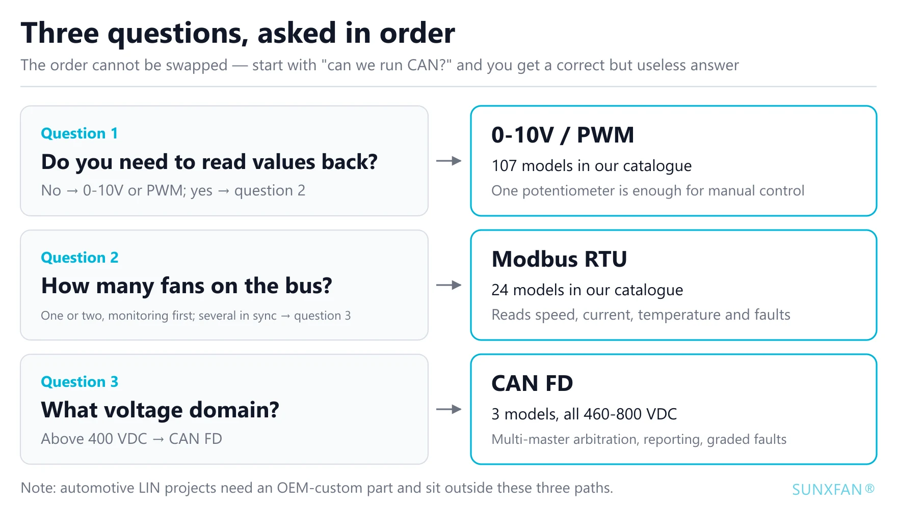
The order cannot be swapped. Start with “can we run CAN?” and you arrive at “CAN is best”, a conclusion that is both correct and useless.
One engineering detail that gets missed
Whichever interface you choose, “what does the fan do when the signal is lost” must be confirmed per model and written into the technical agreement. The three common behaviours are run at full speed (protecting the heat source first), hold the current speed, and stop. On thermal safety those are three completely different devices, and “it usually goes to full speed” is not a safe assumption — behaviour can differ between models and between firmware versions, so this one has to come from the datasheet or from engineering, never from habit.
LIN is the same story: the protective action after a communication loss is agreed between OEM and supplier, and is not in the specification.
Bottom line
There is no best speed control interface, only one that matches what this fan needs to know. 0-10V, PWM and fixed gears are commands; LIN and Modbus are sessions; CAN FD is negotiation. They sit on different tiers, so the question of one replacing another does not arise. Answer “does it need to talk” and “who makes the thermal safety decision” first, and the interface falls out of the answers.
If you need a specific model’s control range, PWM frequency window or lost-signal behaviour confirmed, send the fan model and the controller model and we will work out the wiring and the parameters with you.